


Mambo 6H30pi Preamp
The Mambo Foreplay Project... What was I thinking? Somebody stop me, I'm running amok!
The idea was not to make the circuit more complicated, but instead to clean up the supplies and grounds as much as possible. The good thing about this project was, aside from the C4S transplant, I ended up with two preamps when I finished - a 'boutiqued' Foreplay, and the 2-box monster Foreplay. Maybe I'll be able to run some comparisons and report on that here... eventually
All of this was not about the Foreplay. I just wanted to see how far I could push this thing before I imploded (or my bank account did anyway). The Foreplay is an incredible design and works very well, so this new amp still uses the basic VA/CF circuit Doc and George Wright worked out. If you are considering buying a Foreplay - go do it! I never could have built this thing without building and modifying the Foreplay first. This latest version would be a very expensive kit with all of the chi-chi components, as well as time-consuming to build. Once I get this thing sorted, I plan to convert the old Foreplay into a headphone amp (That'll make an impression at work!), it's still that good.
One important thing about adapting a new layout and power supply is that you get much smarter as you go, and *will* end up rebuilding the thing several times. I'm currently on revision 3 and planning a revision 4 modification.
My thanks go out to all the denizens of the Bottlehead Forum who have offered such great advice, ideas, and entertainment to all of us. I planned to build another web page with details on all of this crazy project way back in April, but then the motherboard on my home PC (a venerable 233 MHz MMX) decided to tank. Lotsa pooched-out electrolytics along the bottom edge of the board! One thing leads to another, but now I'm back in the saddle with a new 550MHz P3 and here's a quick swipe at some documentation on this project... Any feedback is welcome!
Later, pRC
Disclaimer:
(Again) Tubes mean big voltages. Big voltages can stop your heart and kill you.
Be careful! Follow all the suggestions of folks who are wiser than me and don't
even try this if you don't know what you are attempting.
Be responsible for your own actions and don't sue me, OK?
In this page:
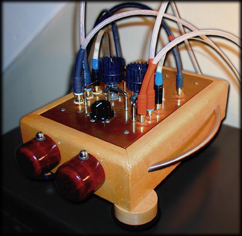
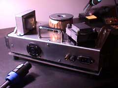
3/4 View: Mambo Foreplay preamp (signal head)
Copper Chassis Plate / Cardas RCA Jacks / Pearl Tube Coolers / Birdseye Maple Frame with SS Handles,
ET Entwined, Goertz Sapphire, and hand-made silver interconnect cables.
Project Summary
Separate Power Supply
I'm now running the third version of a separate Power Supply for the Foreplay.
This uses cables to bring in conditioned DC for both filament (6.3VDC) and
B+ (274VDC plate) voltages. Other features:
- Toroidal transformer for B+ (220 VAC 60VA conditioned to 274 VDC for 6N1P, 204 VDC for 6H30pi)
- Separate transformer for filament (8 VAC, 3.5 Amp Tamura conditioned/current regulated to 6.3 VDC)
- Isolated ground for Filaments to allow floating above signal and amp grounds
- Provide regulated filament current options for 12AU7 (300mA/tube) and 6N1P (600mA/tube) and 6H30pi (825mA/tube)
- Aluminum case for PS with Sorbothane resonance dampening, clear Acrylic bottom plate
- 'Buddha'-fied CMC filtering on line AC and in B+ circuit
- Rectifier snubbers for B+
- High quality film capacitor / choke filter topology for B+ (CRCRCLCLC for 6N1P, RCLCLC for 6H30pi)
- Tie-downs for capacitors with sorbothane pads for resonance control
- Lynk, Mills, and Vishay/Dale wirewound resistors
- Foamed Teflon insulated 18 gauge copper Co-ax cabling to preamp
- Neutrik 'Speakon' 8-conductor connector for umbilical on PS, hard-wired to Preamp head
- Rubber footsies
Chassis Upgrades
I used a heavy copper plate to replace the preamp chassis plate
since I didn't need the original holes for the current PS parts.
- Heavy copper (12 gauge, or 0.10 inch thick) chassis plate
- Sorbothane dampening layer backing
- Moved jacks and tubes back towards center of plate
- Teflon sleeved 20 gauge silver inside preamp head for B+
- Foamed Teflon over 18 gauge co-ax inside preamp to bring power to filaments (stripped Belden 1506A with copper mesh shielding)
- Dual-mono final filter choke and capacitor B+ stages in preamp chassis (1.5H choke and Hovland-bypassed 47uF Solen cap for each channel)
- Voltage network on filament feeds to raise filament voltage to 105VDC for 12AU7 and 6N1P, not required for 6H30pi
- Goldpoint mono volume Attenuators for -60 to -0dB range
- Hand assembled foamed Teflon insulated 20 gauge silver co-ax cabling from attenuator to tube input tabs with copper mesh shielding and double RF filter Ferrite rings
- Yet another Reworked ground bus using the 'Buddha' Single Point Ground from Valve Volume 7, Issue 2. Shielded ground wires, yadda, yadda.
- Separate grounds for Filament and B+ areas back to PS
- Separate chassis ground line back to PS (not used any longer)
- Changed operating points for tubes to get into a higher power plate and current range (10 mA bias, 274VDC B+)
- Biased C4S boards to full 2mA current for better linearity
- Added 2nd aluminum angle support at back of chassis plate for reinforcement, mounting B+ chokes, and umbilical attachment
April 2K Progress Report: Revision 1 version online
Used Panasonic TSHA electrolytic caps in B+. Started layout and parts ordering in January, and it took until now to get everything built and running. Had problems with initial filament filtering and DC voltage regulator, ended up junking the first reg in favor of another design (Cannibalized a Velleman kit for PC board and heatsink). One of the copper foil/oil output caps I used went bad and went back to Hovland caps as replacements.
May 2K Progress Report: Revision 2
Rebuilt B+ filtering with Solen film caps and CLCLC topology. Added a Buddha-style CMC at first inductor per Afterglow article in Valve. Replaced bypassed electrolytics in preamp head unit with a small inductor and dual Solen film caps.
June 2K Progress:
Power Supply fuses start to blow. No time to debug unit, so the original Forplay returns to the main system sans C4S.
July 2K Progress:
Finally have time to sit down with the PS and find that the B+ XFMR line side is blown. Cannot repair the original, and must order a replacement. Will also fix the indicator lamp and add a second power switch for controlling B+ separately on power-up. Started finishing set of wood volume knobs for head unit.
August 2K Progress:
Ordered a replacement high-voltage transformer from Plitron. 220V 60VAC - yeah, it's overkill but I can always re-use it for something else and the larger size will give better regulation. Reading the new issue of Valve, I decided to tear down the head and rebuild with the single point ground described by Buddha. Also decided to change to 6N1P valves - at this point it would be a nearly new preamp.
September 2K: Revision 3
Conversion to 6N1P takes two weekends to get both boxes torn down and rebuilt.
PS - Rebuilt AC entry and added separate 2nd switch for B+ XFMR. Replaced neon power indicator with 6V incandescent in holder wired to filament supply. Re-worked shielding on AC lines. Used clear RTV to insulate filament XFMR connections. Spent a lot of time with Duncan Amps's PSUD2 software and added a 10uF cap on the front of the PS along with 2 Vishay/Dale power resistors to clamp down the voltage before filtering (initial check-out B+ was 304VDC). B+ filter topology is now CRCRC[CMC filter]LC - cable - LC
Head - Tore down chassis to almost bare metal. Added SPG (single point ground) made from a piece of copper plumbing pipe (if I had it to do over would have used thinner copper, that thing made a great heatsink, really tough to solder the last few wires!). Added 2nd 1.5H choke and split B+ before entry to make last stage of filtering dual-mono. Added Voltage Network to Filaments with a 221KOhm Caddock resistor to each leg of the dual-mono B+ (between choke and last cap). Added copper foil tape buss to rear of chassis and connecting to SPG for Filament voltage divider ground reference. Changed last caps to vertical to connect their negatives directly to the SPG. Bypassed Solen 47uF caps with Hovland 0.10uF caps. Hand-assembled shielded twisted-pair for Filament power to tube sockets. Installed sheilded ground conductors made from Belden 1506A coax with clear heatshrink instead of OEM covering. Foamed Teflon over 20 gauge silver conductors for signal lines from RCA input sockets to selector switch and attenuators. Hand-assembled shielded coax with 20 gauge silver conductors for signal lines from attenuators to tube sockets with doubled Ferrite rings at socket tab.
October 2K Progress Report: Revision 4
Ordered four 6H30pi tubes for evaluation. Required some changes to operating points since they do not have the high voltage capability of the 6N1P, and also require 825mA of filament current for each tube. Pinout is the same. Added Schematics to this page (but the PS schematic still shows the fil regulator).
PS - added padding resistors to B+ after rectifier to reduce output to 204VDC. Replaced post-rectifier snubber caps with ceramics. Removed filament voltage regulator since 2 x 825mA = 1.65A which is beyond rating for 7805 - added another 10,000uF filter cap and padding resistor to yeild 6.2VDC by trial and error.
Head - removed high-voltage leg of filament voltage divider since 6H30pi is rated for 250V cathode-heater potential and B+ is only 204V.
Result - 6H30pi has improved sound over 6N1P! New problem - buzzing sound when both attenuators are set to zero position.
November 2K Progress Report: Revision 5
eMail with VoltSecond indicates that the buzzing at zero volume positions may be a parasitic occillation when the input resistance is removed (at zero, all input signal is shunted to ground). I've also been thinking of simplifying the B+ topology by removing an RC filter stage before the choke to reduce the PS impedance.
PS - simplify B+ filtering. Add dual mono filament current regulators and hook up unused 3rd (spare ground) coax line in umbilical to bring that line into head unit.
Head - Add tantalum shunt resistors to attenuators. Add 1.1k ohm tantalum resistors at grid pins to correct buzzing and convert attenuators to shunt mode per VoltSecond (controls parasitic occilations). Add a 220 ohm tantalum resistor to connect VA to CF input for possible parasitics in second stage. Separate filament feeds to connect dual mono current supplies. Add bypass diode to CF input to protect tube during powerup. Up the C4S current to 20mA per tube section for better linearity.
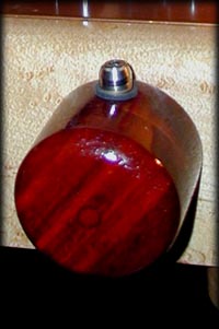
I finally install the paduak volume knobs I've had sitting around forever. To hold the knobs in place and also visually indicate the rotational position I install 8-32 threaded brass inserts and use stainless socket-head cap screws with trim rings that project from the sides. (see new picture at top)
Need to revise the schematics now...
Listening - much better, less microphonic, smoother and fuller sound. I am really happy with the sound of the system again. But, the 13dB T attenuators I added before the Goldpoints are a little too much. The lowest two Goldpoint settings are inaudible and comfortable listening level is at 1 o'clock.
This month I also reworked the Pro*Ject 6.1 turntable - rewiring the arm with Cardas 30 gauge Litz wire running directly into half meter connection cables with no solder joints between the headshell and the RCA jacks at the phono preamp. Also machined a replacement counterweight with a lower center of gravity and setscrew attachment. Replaced the motor with a new unit from Sumiko and rebuilt the AC filter with an ET-style 12 ga braided power cable. Woo-hoo!
Next, I am thinking of two projects - 1) Rebuild the PS chassis to match the head unit and reduce the overall size. This will require a lot of thought to mount all of the iron and capacitors in a 6x10 inch space! 2) Build a second head unit with a single 6H30pi tube, both channels using a single VA stage with transformer coupled outputs (possibly both balanced and single-ended connections?). This will be costly since I'll need another C4S kit, a second set of attenuators, and the output iron. But it would be interesting...
February 2K01 Progress Report: Revision 6
Per Tom Stoppleworth's single stage 6H30pi schematic, I have removed the cathode follower circuit from the preamp. During the modeling for this I discovered that the 100k input attenuator value was rolling of my top end to the poit where I was down -3 dB at 19,000 Hz. Yoiks!
PS - Unchanged, but cutting the load in half raised the B+ to 240 VDC...
Measurements:
B+ at C4S input - 240.5 VDC and 0.3 mV! AC
Head - Removed connections and C4S cathode sinks from each channel. Rewired the right channel to mirror image the left so that tubes can be swapped to use either section evenly - right channel uses right section, left channel uses left section. Removed 100k goldpoint attenuators and installed a 50K ALPS stereo pot with 56k tantalum shunt resistors at input. Also moved the selector switch to the second front control position. There sure is a lot more room in there with only one pair of C4S and connections.
Measurements:
Plate input - 96-103 VDC (varies by tube)
C4S current - 20 mA
Cathode Bias - 4.25 VDC
Cathode Hum - 0.2 mV AC (!)
Output Hum - 0.8-3.0 mV at max output from a shorted (4k R) input (varies by tube)
Max Output - ~6 VAC
Still in burn-in, but sounds more open and with more treble on hand, also less hum. Planning to replace the stereo pot with a stereo attenuator once I measure the existing resistances at normal and max volumes. (measured at 6K wiper to GND at amp clipping) I guess I could also use a 50K 10-turn WW pot since 5k - 0 would be one the last turn, or first turn, depending on how it's connected!
I measured all 4 of my 6H30pi tubes in-circuit via jumpered-in flying leads (makes a helluva tube tester) and found that the left sections (pins 1/2/3) are a little noisier than the right side (pins 6/7/8) when using only one side on all tubes tested by about 2mV AC. Hrm. Of the 4 tubes, one was better balanced L/R with more gain than the others so I'll save it for a future one-tube driver for a headphone amp I'm planning. From the other 3 I was able to get a good match for the 2 sides. By mirroring the circuit and using only one side of each tube I hope to be able to swap periodically and extend life (plus, it was easier than making a new chassis plate).
Comparisons?
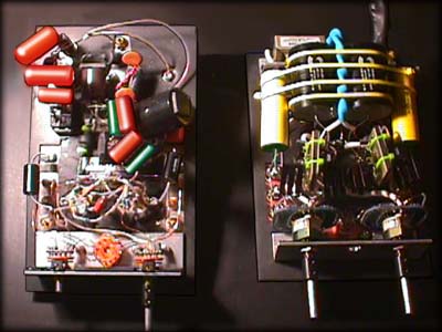
Comparison between Original Tweaked Foreplay and the Rev2 Preamp Head
More crowded, yet most of the PS is elsewhere!
Below: Rev3 up close
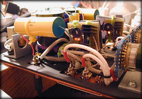
Rev 3 Preamp Head:
Back-to-back C4S, Goldpoint Attentuators, Cardas Jacks, Shielded Grounds, Silver Signal Wiring
The Preamp 'Head'
Preamp head unit has another LC filter for the B+, and another cap stage for the Filaments. The rest is the familiar Foreplay layout, but using a 0.100 inch thick copper chassis plate backed with sorbothane, front volume attenuators, and star grounding back to the final B+ ground. Chassis is grounded using the yin/yang diode method back via a separate ground line to the PS.
![]() Rev3 [6N1P] VA/CF Preamp Head Schematic
Rev3 [6N1P] VA/CF Preamp Head Schematic
![]() Rev4 [6H30pi] VA/CF Preamp Head Schematic
Rev4 [6H30pi] VA/CF Preamp Head Schematic
![]() Rev5 [6H30pi] Grounded Cathode Preamp Head Schematic
Rev5 [6H30pi] Grounded Cathode Preamp Head Schematic
The preamp head has the final stages for the power supply and rest of the good stuff - a 47uF Solen cap for each channel, a bypassed 10k Panasonic TSHA for the filaments. In reading the C4S manual, it turned out that the gound could be shared between the source and sink boards, so I made 'em into sandwiches with zip ties holding them back-to-back around a piece of Sorbothane, added heat sinks, blah, blah, 2mV operating current, 10 mV current for each tube section, blah. (the 10 mV operating point was decided in a phone call with Doc back in March, the only real calculation was the 12AU7 cathode resistor for the VA stage, which doc rattled off as 350 ohms.
Man, these C4S boards take the hassle out of calculating all those other resistors!). The Preamp also has Cardas jacks, Goldpoint mono attenuators, and a Grayhill selector switch. Basically, except for the C4S boards from the previous Foreplay, it's a whole new preamp. So I installed the stock value resistors in the original to be able to A/B compare them.
So, how did it sound?
Skweaky new, no break-in, I listened to it for 3 hours the first night. I was surprised at the improvement - very dynamic, good spaciousness, but even better - even more involving. Acoustic guitar was just there... already. A little congested sounding with more complex work. I never knew my CD player sounded this good. Man, this is really exciting stuff!
I switched around a few tubes, and could really hear bigger differences between them now.
Downside - system was much more microphonic now, and the tubes were getting really warm (lay your finger on top of one for about 5 seconds and you'd be pulling it off in a hurry). Also, testing the operating points, it was apparent that there is a lot more going on than the old voltages; tubes that used to measure within 3V on the old Foreplay were off by a lot more.
Rev3, 6N1P Valves - How does it sound?
One word: DRIVE. With the new PS configuration and the 6N1P tubes,
this thing is much more dynamic! I calculated the 6N1P cathode resistor at 680 Ohms,
which I thought would be around -2 to -3 Volts, but it measures at 5.3 which may be too much.
As it burns in I am struck by new minor detail in familiar recordings, but the sound is full and rich at the same time.
So far I'm very happy with the sound, but I may change the cathode resistors to a lower value to listen for differences.
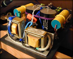
The Power Supply
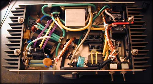
Rev3 Power Supply, clockwise from top center:
Filament Regulator at top center - silver aluminum heatsink for voltage regulator
CMC filter for AC at top right
Filament supply at right and middle
Power Switched at bottom right
High Voltage rectifier bridge at bottom left with snubbers on in and out sides
High Voltage RCLC at left with Solen 47uF caps in view
Neutrik 'Speakon' 8 conductor connector at top left
Copper foil sheilding on AC lines
![]() Rev3 [6N1P] Preamp Power Supply Schematic
Rev3 [6N1P] Preamp Power Supply Schematic
![]() Rev4 [6H30pi] Preamp Power Supply Schematic
Rev4 [6H30pi] Preamp Power Supply Schematic
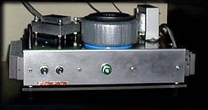
PS box has a Plitron toroidal XFMR for B+ with a CRCRCLC filter, and Filaments are regulated DC from a separate 8V 3.5 Amp Tamura XFMR picked up on sale. This goes through an umbilical with a Neutrik 'Speakon' 8 conductor jack on the PS case. Umbilical cable is 3 spiraled Belden teflon video coax lines, hard-wired to the Preamp chassis, and covered with mesh tubing.
Wow! Have I learned a lot about power supplies on this one? And yet I've barely scratched the surface. Got the first version up last weekend and had probs with both the high voltage (too much) and the regulated filament voltage (too little). Hrmph. Back to the drawing board. After poring over Buddha's Afterglow mods more, I decided to basically rip everything out and start again...
So instead of big Panasonic TSHA caps in the B+, I went to all 47uF Solens and added another 1.5 Henry choke I had around between the 2nd and 3rd stage caps. Also added Buddha's CMC after the initial choke and added some wirewound resistors before the L to get the voltage down to 300VDC. Installed and running I'm getting a little less than 3mV AC after the end stage.
Tossed my initial terminal strip LM317T regulator and replaced it with an adjustable setup around a 7805 with a big-ass heatsink that doesn't even get warm now. Will return to the earlier model and debug it just to find out what was up (love a good mystery? or Anal retentive? Me?).
Added one of Buddha's CMCs on the wall input (hey, I ran out of room!) and built a full version as a power box later. Doc Bottlehead sez that the first stage gets you 90% of the low-pass filtering anyway. Testing with a coupla resistor loads showed that I had headroom with the Filament current for a 6N1P later (double the current of a 12AU7 at 6.3VDC). Running with the 12AU7 I was getting right at 3mV hum at the tubes (Dang, there's that 3mV number again).
Got everything all installed, and added copper tape sheilding on all the internal AC lines and transformer ins and outs. Running all of the grounds (all the transformers and connections are isolated) to a central point, then connecting to the chassis at the IEC input jack. The chassis ground system then bridges to the HV ground and an isolated ground jack via the double ying/yang diodes Doc suggested.
All of the power goes to the preamp chassis via triple Belden 18 ga solid core foamed teflon coax wound together into a bundle and covered with black cable mesh. The connector is a Neutrik 8 conductor 'Speakon' mounted on the PS, with the other end hard-wired into the preamp. I ended up using a lot of the Belden coax for internal PS wiring after stripping off the sheild - makes really nice 18 ga wire and the teflon foam won't melt when you solder it. The core is 5 or 6 9's copper, Decent stuff.
Output Capacitors and the Foreplay
Does switching Output Caps on the Foreplay make any difference? The short answer - Yurp, they make a difference.
From what I've read, the value of the output cap affects the low frequency rolloff point of the circuit, while the quality and construction of the cap affects everything else.
While it's probably one of the easiest parts to swap out (being on the outside of all those wires, especially if you solder on a pigtail to the output tab of the sockets), it's hard to evaluate caps quickly because they really need to break in for a coupla weeks before they are running optimally. There seems to be some controversy on burn-in or break-in and sound, but physics supports this strongly.
The physicist Richard Feynman wrote a lot about the 'principle of least effort', which is the physics law that energy always takes the easiest path. He used this to explain, among other things, why light refracts through water and how to calculate refraction through different materials.
Stretching the water metaphor to it's breaking point, if you think of the capacitor as a different medium, refracting the current, then add in the fact that the energy moving through the capacitor's materials will alter the alignment of it's molecules, we can start to see how the cap break-in works. The electricity realigns the dielectric and conductor materials over time into a 'least effort' arrangement, which removes residual harshness and improves dynamics (within reason).
This is probably also why some materials (and construction styles) sound better. Steve Bench and Walt Jung and many others have written about the sound of different dielectrics.
http://members.aol.com/sbench101/
http://www.capacitors.com/pickcap/pickcap.htm
So, you can order a few and swap out those babies and listen for yourself. As you have probably seen at various sites, film caps in this range run from $2 (Solen) to $10 (Kimber) to $30 (Hovland and Jensen) to $60++ (Audio Note, scary). For the common brands, see Quest' post on the next question down from the forum entry page... The stock caps are polyester film caps, 2uF. You can probably use anything from 1uF to 10uF, rated to minimum 100VDC and not get into trouble (Doc? this was discussed before?), output voltage from the CF on the stock Foreplay is about 50VDC, so this will give some safety headroom.
I've tried Solen 2uF and Hovland Musicap 3uF in my Foreplay, and they both sound damn good after break-in (the Solens seemed to take longer than the Hovlands to develop). Both had good bass in my system (the Hovlands a skooch more with better control), but I also run single-ended MOSFET power amps, so YMMV. In the first version of the Mambo Foreplay I trying some 1uF Angela/Jensen copper foil/paper/oil caps to hear how they sounded, but one of them was bad and made noise, so I'll restrain myself from venting more opinions on ya. Back to the Hovlands for me. In general, folks say that foil and polypropylene caps sound cleaner and faster, and paper/oil caps sound 'lusher'.
One good thing about switching caps is that, like tubes, the differences are audible. You can use this to tailor your output to the amps and speakers for the sound YOU like best.
BTW, Doc told me that he did not [personally] like the sound of the 'Multicaps' in the Foreplay, but thought the multiple-parallel-capacitor design sounded a little 'smeared' to him. You may want to keep this in mind if you try to bypass the coupling caps with multiple values...
The caps that have lived in this amp the longest are the current ones (22 months and counting) 0.22uF Western Electric paper in oil caps, NOS purchased from Angela sometime back. With the 6H30pi a much smaller output cap can be used. After living with a variety of plastic caps for a long time I decided that these let me enjoy the music a little more... and I got tired of messing with the circuit when I had other projects beckoning.
Hey, this is the fun stuff!
Good luck and let us know if you find any 'wundercaps' we should all try.
Headslappers
Besides having to totally rebuild the PS? Twice? OK, three, no wait, four times?
I had to rebuild the connecting cable 3 times to get the shrinkwrap in place correctly and all of the parts for the connector in order... Don't forget to put the locking ring over the cable *before* you solder the cable jacks!
Buy a couple of spare soldering iron tips (or 7) to have on hand in case you space out and leave the iron on overnight and cook the solder off - it's much easier than trying to get the old tip back into condition (it's never really the same afterwards).
Don't try using a CMC as an inductor by wiring the sections in series (it had a transformer effect and raised the filament voltage by 2V).
Somehow I wired up the selector switch wrong the first time so that the inputs were paired correctly but the center position was the back set of inputs. Dang! And the neon lamp for the power-on indicator was not working in Rev1 or Rev2.
When I added the SPG (single point ground) to Rev3 I used a flattened section of 3/4 inch copper plumbing pipe. This turned out to make a fantastic heatsink that took an insane amount of heat to get a quality solder joint, especially once things started getting tight in there. Lesson learned: Use a smaller, thinner piece of copper next time. (Later... Aha! the adhesive copper tape used for stained-glass work is perfect!)
What's Next?
Now I have about nine 12x16 plastic bins filled with parts and enough experience to really hurt myself - soooooo... How about a really scary looking Headphone amp for the office system? Yeah!
Thinking about this and doing research on the Headwize site I'm wondering about using an output transformer, so I've ordered 3 different inexpensive audio transformers from Allied and Mouser to try some ideas before I commit to quality iron. Other ideas - a 2A3 output stage? ET Paramours on a single chassis? A switchable blend circuit? A shunt stereo attenuator?
In the meantime I plan to finally finish and install the wood volume knobs on the Mambo Foreplay, along with a birdseye maple front plate for the PS.
Or maybe a set of DIY Voigt pipes?
Still saving for that pair of Parabees,
pRC (March Y2K)