

| Sorry about the mess - Send me eMail if it is too horrible! This is a long and rambling saga of a 3 year adventure designing and building a strange amplifier. If you just want the overview and schematic, go back here. But if you want the gory details, you are in the right place. I had been plotting to build a pair of monoblock tube power amplifiers since the second iteration of the Foreplay kit, but with the house renovations and other distractions I could not scrape together the cash to buy a Parabee kit from Bottlehead, and so the wheels kept spinning... Blah, blah, blah - I hope you read the first page! Holy Cow! Monstro picture directory Here |
||||||||||||||||||||||||||||||||||||||||||||||||||||||||||||||||||||||||||||||||||||||||||||||||||||||||||||||||||||||||||||||||||||||||||||||||||||||||||||||||||||||||||||||||||||||||||||||||
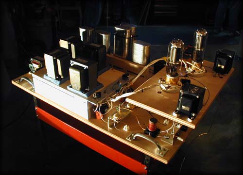
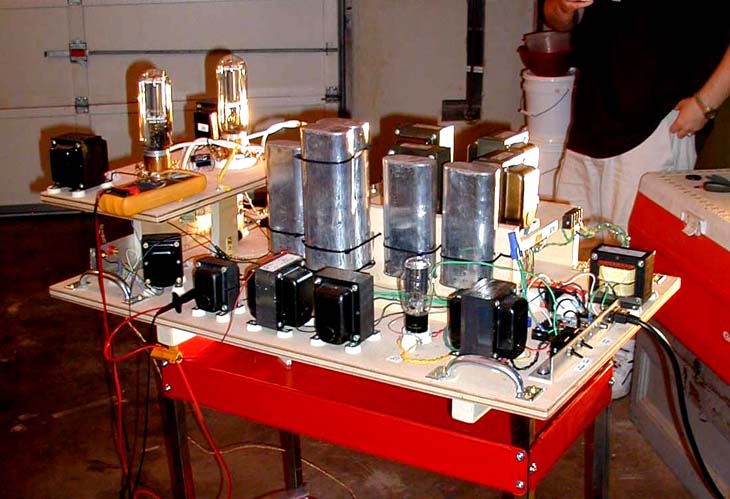
il Monstro is alive! Front: 845 tubes and oneElectron PRC-2 plate chokes, Back: Lots of huge GE oil caps and B+ chokes, Left: Filament supply with CLCLC filters. |
||||||||||||||||||||||||||||||||||||||||||||||||||||||||||||||||||||||||||||||||||||||||||||||||||||||||||||||||||||||||||||||||||||||||||||||||||||||||||||||||||||||||||||||||||||||||||||||||
|
D i s c l a i m e r:
Tubes mean big voltages. Big tubes mean bigger voltages and even more current than most tube amps. The voltages in this amplifier design can stop your heart and kill you. Be careful! Follow all the suggestions of folks who are wiser than me and don't even try this if you don't know what you are attempting. Take responsibility for your own actions and don't sue me, OK? |
||||||||||||||||||||||||||||||||||||||||||||||||||||||||||||||||||||||||||||||||||||||||||||||||||||||||||||||||||||||||||||||||||||||||||||||||||||||||||||||||||||||||||||||||||||||||||||||||
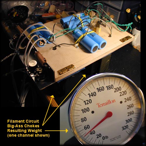
Filaments: Circuit uses separate CLCLC filament supplies for each 845 using Schottky bridges, mammoth 15mH Hammond chokes and 10,000 uF C-D Caps. One channel of breadboard filament supply weighs 47 pounds without the power transformer. |
||||||||||||||||||||||||||||||||||||||||||||||||||||||||||||||||||||||||||||||||||||||||||||||||||||||||||||||||||||||||||||||||||||||||||||||||||||||||||||||||||||||||||||||||||||||||||||||||
| September 2001 | ||||||||||||||||||||||||||||||||||||||||||||||||||||||||||||||||||||||||||||||||||||||||||||||||||||||||||||||||||||||||||||||||||||||||||||||||||||||||||||||||||||||||||||||||||||||||||||||||
|
VSAC 2001 - the most fun I have ever had at a conference on any subject! Found the Sakuma design and started noodling on a parafeed adaptation. This design will use massive amounts of iron, so some creative approach to parts and/or financing will be needed. The key circuit inspiration for this amp is a Sakuma design using an 845 to drive an 845: Lots of other 845 projects can be found online, and some are published - Sound Practices showed a version of J.C.Morrison's Dinosaur 50 amp with 845 tubes running at low voltage. Conflicts in Parafeed implementation strategy: from Doc B. The size of the parafeed coupling capacitor is influenced by the whichever of the other two parallel elements in the parafeed network has the lowest impedance at low frequencies. So no matter how high the inductance of the output transformer, if you use a plate load with a low frequency impedance/inductance lower than the inductance of the OT (which would also be much lower in comparison to something like the C4S load), the plate load determines the cap size, not the OT. |
||||||||||||||||||||||||||||||||||||||||||||||||||||||||||||||||||||||||||||||||||||||||||||||||||||||||||||||||||||||||||||||||||||||||||||||||||||||||||||||||||||||||||||||||||||||||||||||||
| November 2001 | ||||||||||||||||||||||||||||||||||||||||||||||||||||||||||||||||||||||||||||||||||||||||||||||||||||||||||||||||||||||||||||||||||||||||||||||||||||||||||||||||||||||||||||||||||||||||||||||||
|
After a few false starts I come up with the first version of the circuit: The most expensive part of this design will be the iron, and there is a lot of it. Should make Mikey LeFevre of Magnaquest very happy. Starting with the sticker shock from the Tamura quote, I set out to compare several alternatives, a couple of which are listed below. Building the design using the budget iron listed would be an interesting project all on it's own, but I chose to take the middle road and spend a little extra on the signal path iron, while trying to save some cash on the filter chokes and power transformers. After a long and enjoyable evening conversation with LeFevre, he convinced me to try the 'Vintage' Peerless input tranny in an octal package and also one of his newer devices, a center-tapped high quality choke in place of Sakuma's interstage transformer. In combination with the parafeed loading of the driver tube, this should provide a simpler connection to the grid of the output tube and a more immediate sound...
|
||||||||||||||||||||||||||||||||||||||||||||||||||||||||||||||||||||||||||||||||||||||||||||||||||||||||||||||||||||||||||||||||||||||||||||||||||||||||||||||||||||||||||||||||||||||||||||||||
| December 2001 | ||||||||||||||||||||||||||||||||||||||||||||||||||||||||||||||||||||||||||||||||||||||||||||||||||||||||||||||||||||||||||||||||||||||||||||||||||||||||||||||||||||||||||||||||||||||||||||||||
|
Order 845 tubes and sockets, 83 rectifiers. |
||||||||||||||||||||||||||||||||||||||||||||||||||||||||||||||||||||||||||||||||||||||||||||||||||||||||||||||||||||||||||||||||||||||||||||||||||||||||||||||||||||||||||||||||||||||||||||||||
| January 2002 | ||||||||||||||||||||||||||||||||||||||||||||||||||||||||||||||||||||||||||||||||||||||||||||||||||||||||||||||||||||||||||||||||||||||||||||||||||||||||||||||||||||||||||||||||||||||||||||||||
|
January, start ordering parts...
An aside on plate chokes and finding them... |
||||||||||||||||||||||||||||||||||||||||||||||||||||||||||||||||||||||||||||||||||||||||||||||||||||||||||||||||||||||||||||||||||||||||||||||||||||||||||||||||||||||||||||||||||||||||||||||||
| February - March 2002 | ||||||||||||||||||||||||||||||||||||||||||||||||||||||||||||||||||||||||||||||||||||||||||||||||||||||||||||||||||||||||||||||||||||||||||||||||||||||||||||||||||||||||||||||||||||||||||||||||
|
February, order more parts...
With feedback from Mikey and Dowdy - Changed the interstage transformer to an EXO-173 center-tapped autoformer per Mikey; added chockes to the ground lines of the filament supplies per Jim Dowdy to filter out the transistor rush from the Schottky bridges. Order Magnaquest iron from Bottlehead.com Order Oil caps... |
||||||||||||||||||||||||||||||||||||||||||||||||||||||||||||||||||||||||||||||||||||||||||||||||||||||||||||||||||||||||||||||||||||||||||||||||||||||||||||||||||||||||||||||||||||||||||||||||
| April 2002 | ||||||||||||||||||||||||||||||||||||||||||||||||||||||||||||||||||||||||||||||||||||||||||||||||||||||||||||||||||||||||||||||||||||||||||||||||||||||||||||||||||||||||||||||||||||||||||||||||
|
Ordering more parts...
More Refinement - Parts piling up in basement... Input from Paul Joppa on parafeed op points - |
||||||||||||||||||||||||||||||||||||||||||||||||||||||||||||||||||||||||||||||||||||||||||||||||||||||||||||||||||||||||||||||||||||||||||||||||||||||||||||||||||||||||||||||||||||||||||||||||
| May 2002 | ||||||||||||||||||||||||||||||||||||||||||||||||||||||||||||||||||||||||||||||||||||||||||||||||||||||||||||||||||||||||||||||||||||||||||||||||||||||||||||||||||||||||||||||||||||||||||||||||
|
Order buttload (8) of huge and very heavy Hammond filament chokes...
80+ pounds when they arrive - I can hear the UPS delivery person huffing them up the driveway.
May, start building the breadboard! It's big, it's really big, it's huge... it's not big enough. I started with a 24 x 42 inch slab of 3/4 inch birch plywood with big handles bolted onto all four corners and a cheap rolling shop cart under it to raise it up waist-high. I ended up double-decking the filament and 845 tube areas to be able get all of the parts onto the board. Late June, found a diode biasing idea from Steve Bench's site - 845 based No R No C Amplifier Bench uses a glow tubes to bias his 845 tubes, using an 0C3 for 40mA bias current, or an 0B3 for 65mA. The only problem with this is that it will take 105V to spark the diode tubes, and this is 60V higher than the original Sakuma design - it's not a matter of increased current but of what my final B+ will be with the transformers and filters. I believe I will have some headroom, but I just won't know until the circuit is fired up. So I wired octal sockets into the grounding path - without the tubes there is no connection. If I want to test the diode biasing I can remove the GND connection from the bottom of the cathode resistors and insert the 0C3 or 0B3 glow tubes. |
||||||||||||||||||||||||||||||||||||||||||||||||||||||||||||||||||||||||||||||||||||||||||||||||||||||||||||||||||||||||||||||||||||||||||||||||||||||||||||||||||||||||||||||||||||||||||||||||
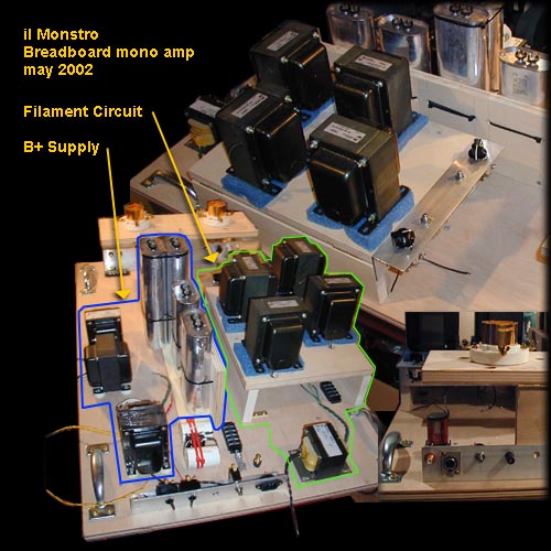
Breadboard, mid-May 2002: To give a sense of scale, the plywood is 24 inches by 42 inches, and had to be double decked to fit all of the components. 845 sockets are at the far end, GE oil caps for B= run up the center, and iron is arranged along the sides. 83 rectifier is not installed in these shots, sorry. |
||||||||||||||||||||||||||||||||||||||||||||||||||||||||||||||||||||||||||||||||||||||||||||||||||||||||||||||||||||||||||||||||||||||||||||||||||||||||||||||||||||||||||||||||||||||||||||||||
| June 2002 | ||||||||||||||||||||||||||||||||||||||||||||||||||||||||||||||||||||||||||||||||||||||||||||||||||||||||||||||||||||||||||||||||||||||||||||||||||||||||||||||||||||||||||||||||||||||||||||||||
|
June, debugging and trying different circuit ideas...
It doesn't spring from your brain working perfectly, it takes some work.
A few days in the life as I prepare for the Dixie Bottlehead Summer meeting at Phil Seig's
in Knoxville (now THIS is motivation).
Sunday, 7jul02: 5 hours to install the cathode bias system along with the diode bias tube sockets pre-wired and waiting. Chopped down the filament coax and stripped back the insulation to hookup to the brass thumbscrews I installed in the 845 sockets - taa Daaa! I finally get everything hooked together and fire it up with a variac... Fils are low - only 8 volts DC. I install an 8 ohm 10W power resistor across the output terminals and cautiously fire up the B+. Hook up an old Pioneer full-range naked to the output. Monday, 8jul02: OK, so it's all together on one chassis and can be plugged in without smoke escaping! So, here are the problems solved: 1) With my variac subbing for the filament trannies I'm getting 10V with 18VAC input. Back to the catalogs for me. Filament trannies need to be 18VAC output with the CLCLC filtration, not 12.6VAC as I bought. 2) I have a tube clearly marked '83' which has a different structure than my 3 other 83 tubes, and does not glow purple when in-circuit, and does not rectify. This is not an 83? Of course, that was the first rectifier I tried and spent 30 minutes trying to figure out what was wrong with my B+... 3) Another problem overcome is the need for the interstage choke to have a blocking cap to protect the output tube from grid current - man, it was drawing current like a wild thing when I had the choke fitted ultrapath-style with the cap on the bottom. Everything seems stable now. But, it's also a hum monster and the filament trannies I have are too low in voltage. I'm reading only about 5mV hum in the fils at the the sockets. B+ is 470+ at the 83, and about 397VDC at the output tube and 374VDC at the driver tube. But I'm putting out 5V at 120Hz into my 8 ohm test speaker. Dang. Have a lot of AC showing up where it shouldn't - 10-11VAC between the driver fils and signal ground. ...even 69VAC between the middle of the output tube plate choke and the B+ ground. Hrm. I need to go think on this some, but I'm wondering if I have some bad filter caps for my B+? I will start disconnecting and measuring subsystems tomorrow - 1) Filaments (break ground between signal and B+, disconnect plate and grid wires from tube sockets) 2) Add connections back between B+ and signal GNDs and search for hum on B+ side 3) Disconnect signal GND from B+, remove tubes, and measure B+ under no load Tuesday, 9 July 02 eMail to Paul Joppa, Phil Sieg, Jim Dowdy OK, 3 more hours in the un-air-conditioned garage sweating and walking in circles and I'm a tiny bit closer. Maybe. Discovery Number 4) Those little car audio chokes I put on the grounds for the filaments were screaming hot when I checked them today, so they are out of there. After I removed these parts the potential between the fils and B+ GND went down from 9.77VAC to 28mVAC! (well, 28mV from the Driver fil, but 23mV from the Output fil). Without those parts the input voltage needed is down to 15VAC. Good thing I didn't order replacement trannies yet... Number 5) The AC voltage seems to be related to a potential between the 2 dedicated filament supplies - not sure how this can be as the circuits are totally parallel, but when I disconnected the common grounds I found 655 mVAC between them - solution? Maybe tie the ground busses between the two filter sections together at each capacitor section? Good news - the filaments, when measured individually, have low hum: 0.7mV for Driver, 0.8mV for Output tube after spinning the hum pots a little. Number 6) Installed pigtails on all of the B+ oil caps with crimp-on spade connectors so I can safely get readings. Here are the current B+ numbers:
                              ----------------- Choke - 845 Output
                              |                  48H    377VDC
                              |                 304ohm  177VAC
Rec                           |
83 -- C --- L --- C --- L --- C --- L --- C --- Choke - 845 Driver
     24uF  10H   24uF  10H  120uF  12H    |      48H    355VDC
      |   82ohm   |   82ohm   |  155ohm   |     304ohm   44VAC
    492VDC      467VDC      438VDC      412VDC
     23VAC     1.025VAC    0.237VAC    0.396VAC
Soooooo... B+ filtering is looking good up to the 12H L, where I'm picking up noise? 44VAC at plate of Driver is being amplified by output - 44VAC X 4 = 176? Ergo: Gotta find the source of the 44V 120Hz hum. Things tried to no avail - a) Moved parafeed cap ground from top of cathode to signal GND b) Grounding input RCA with 1k ground plug c) Disconnecting interstage autoformer and coupling between tubes via the cap (without a ground reference the output tube oscillated weirdly - visibly gyrations of test speaker, with the 40k resistor GND ref restored the 120Hz returned) Thoughts: 1) Man, those 845s put out some HEAT. This may be a winter amplifier. 2) I wish I had another 100VDC or more at the tubes 3) I think I can lose a filter stage with the 48H plate chokes and still have low noise, but I gotta get the hum out of this thing to be able to measure the true filtration of the oneElectron PRC-2 chokes. 4) My brain is tired - I'm going to go eat now. Paul writes back: The circuit does not show any common ground share by the two filament supplies. Wednesday, 10 July 2002 11:03 PM eMail to Paul Joppa Thanks for picking up on this again; I really appreciate any help you can toss my way - I'll take another crack at measuring the other EXO-50 tomorrow - thanks for clarifying the test method a little, I'm still learning!  The 845 debug process continues - tonite I rebuilt the front end so I
could move the plate chokes up top and far away from everything else.
When I measure the B+ circuit unloaded it is really quiet (0.7 to
1.3mVAC!), and the filament circuit is similarly quiet when the B+ is
off. It's when they are both running that a mysterious 8VAC appears
between the fils and the B+ ground. Yoiks.
The 845 debug process continues - tonite I rebuilt the front end so I
could move the plate chokes up top and far away from everything else.
When I measure the B+ circuit unloaded it is really quiet (0.7 to
1.3mVAC!), and the filament circuit is similarly quiet when the B+ is
off. It's when they are both running that a mysterious 8VAC appears
between the fils and the B+ ground. Yoiks.
Now, since the fils were low on my first pass I had disconnected the original on-board filament XFMR and subbed a variac in it's place - additionally there are a LOT of extension cords in the garage between the amp, the variac, and the wall. I'm thinking that I could be developing the potential AC between the variac and the filtered B+ that was still on the breadboard (1 stage buddha CMC filter at entry). I re-installed the filamnet transformer and was able to get 9.4VDC at the tubes tonite (voltage went up since I removed the chokes from the GND leg). As soon as I get the B+ back together I think the hum numbers will be different, but who knows? Oh yeah, I also added a link between the two filament GNDs at the middle set of caps. While I debug the noise I've installed some 4.7uF/630V Solen blocking caps, they give me more room for poking around and offer less surface area to pick up noise. With the plate chokes moved out there is a lot more room in the center of the board! Thanks for letting me ramble - these eMails help me to think things out and are also a journal of sorts for the debug process that I'll add to my article. I hope it will help some folks to see the mental process, warts and all. Thursday, 11 July 2002 Based on Paul's observation of the current draw (D'Ohhh!) I went ahead and hooked up the diode bias scheme from Steve Bench's site - and it worked!... OK, it worked for 2 tries, and then the diodes would not spark. Dang. Without the diodes in 'glow' mode, the 845s drew no current and the plate voltage went up to 617VDC with the cathodes at 113V. Oh so close. I tried swapping 0C3s but nothing helped. With the diodes working the plate voltage was around 510 (490 for the driver) and both cathodes were at 103V or so... A puzzle, a mystery, an enigma - why would it work the first couple of times? It sure looked cool, I would like to have heard the sound of the amp in this mode. Sunday, July 14, dBH BarBQ and big ass amp shootout between Dowdy's GM70 monster and the 845:845... Sadly, Jim Dowdy had to beg off from coming to the meeting so there was no shootout. But then, I had to lay off debugging the amp for a couple of days due to some job deadlines, so I brought the amp to Phil Sieg's house with the faulty diode bias scheme in place. After demonstrating that the diodes were not igniting we bypassed them and returned the adjustable cathode resistors to the circuit, and I clipped the caps to simplfy matters. Voila! we have bias, tube B+ voltage is close to Sakuma notes, and it makes a sound when we hookup input from a signal generator that sounds pretty dang clean. |
||||||||||||||||||||||||||||||||||||||||||||||||||||||||||||||||||||||||||||||||||||||||||||||||||||||||||||||||||||||||||||||||||||||||||||||||||||||||||||||||||||||||||||||||||||||||||||||||
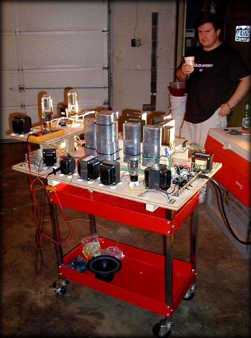
Filaments: il Monstro on the road - Dixie Bottlehead Rick Henthorn savors a fine home-brew ale and hopes that my cheap shop cart holding the breadboarded amp does not collapse in Phil Sieg's garage. Click for larger amp picture |
||||||||||||||||||||||||||||||||||||||||||||||||||||||||||||||||||||||||||||||||||||||||||||||||||||||||||||||||||||||||||||||||||||||||||||||||||||||||||||||||||||||||||||||||||||||||||||||||
|
So we wheeled it into the listening room and hooked it up to Phil's T1 horns... and sound came out but very, very quietly. This stumped everyone. We tried swapping in preamps with more drive, and it got a little louder, but nowhere near to listening levels. We tried clipping out the 100ohm adjustment pot from the Sakuma input circuit, but no joy. What was there was clean, but low amplitude. Phil mused that his 2 stage 45 amps were plenty loud with the T1s, so the 845 amp should be louder - perhaps it was something to do with the step-up input transformer? Monday, 15 July 2002 10:05 PM eMail to Paul Joppa, Phil Sieg, Jim Dowdy Looks like we were only *one* last change away from a working il Monstro yesterday - As we discussed at your place Phil, I came home tonite and looked at the input tranny wiring and Lo, my hookup was all frelled up. It's a wonder that we got any output at all - don't have time to wring it out, but here are the amplitude values with 1VAC @ 400Hz in -
1.0VAC   --+
           |  Peerless 15095 input
5.0VAC   --+
          ( ) 845 Driver
21.81VAC --+
           |  EXO-173ni
21.67VAC --+
          ( ) 845 Output
81.7VAC  --+
           |  EXO-50 output XFMR
32.12VAC --+
         (( )) 8 ohm Pioneer 51W fullrange
By my copy of Audio Gadgets, 32V into 8 ohms is 64 Watts - something is wrong there... And the current supply numbers:
                                ----------------- Choke - 845 Output
                                |                  48H    507VDC
                                |                 304ohm .056VAC
                                |
                                |                        45V Bias
                                |
Rect -- C --- L --- C --- L --- C --- L --- C --- Choke - 845 Driver
83     24uF  10H   24uF  10H  120uF  12H    |      48H
        |   82ohm   |  82ohm    |  155ohm   |     304ohm
      547VDC      537VDC      528VDC      519VDC          497VDC
      8.85VAC    .079VAC     .026VAC     .017VAC         .048VAC

                                                         50V Bias
Looks like I've got some low-frequency resonance occurring - below 9Hz according to the Fluke meter. Will have to hook up the Tek scope and see if I can knock it out by changing caps and/or the loading resistor. Sounds OK through the Pioneer test speaker, but I really need to hook it up to the main system to hear what's music and what isn't later. Paul, I'll measure the 2nd channel EXO-173 and EXO-50 iron this week and report to you. After a disappointing week, suddenly this is fun again - Wednesday, 17 July 2002 10:30 PM eMail to Paul Joppa, Phil Sieg, Jim Dowdy The 845:845 is out there in the Garage playing away - Monday got the thing running pretty well and hooked up the pioneer full-range and a portable CD player - at times it's downright listenable, but I've yet to lug it into the LR and hook it up to the main system. Tuesday I cleaned up the routing and grounded the output of the EXO-50. Got a scare when I tried to use some older Jensen 1uF copper/oil caps in parallel for the output and one was bad - re-inserted the 2uF bathtub cap and thengs are happy in ultrapath mode. Found out the hard way that tying the bottom of the EXO-173 to the top of the cathode was not good - driver went into some kind of loop and started drawing too much current. I attribute this to the autoformer not really having a separate primary and secondary... anyway, it needs to tie to ground. Last night I also tested power and bandwidth and my -3dB points are somewhere around 25Hz and 39,000Hz. So I'll be trying various cathode bypasses on the driver tube first to see if I can get some more bass. Tonite I reinforced the shop cart - no more parallelogramming, woo! I also dragged the scope upstrairs so I can start really looking at residual noise and cap/routing changes. Of course, much of this may be out the window when I try to force the circuits into nice chassis'. Saturday, 20 July 2002 Hooked up my ancient Tektronix 465 oscilloscope to the monster last night and learned some insteresting things. |
||||||||||||||||||||||||||||||||||||||||||||||||||||||||||||||||||||||||||||||||||||||||||||||||||||||||||||||||||||||||||||||||||||||||||||||||||||||||||||||||||||||||||||||||||||||||||||||||
| August - October 2002 | ||||||||||||||||||||||||||||||||||||||||||||||||||||||||||||||||||||||||||||||||||||||||||||||||||||||||||||||||||||||||||||||||||||||||||||||||||||||||||||||||||||||||||||||||||||||||||||||||
|
Start building the chassis frames and cutting copper top plates... Whoa. Hold up there, partner. My company decided that I should move to Charlotte, NC and informed me of this on 24 July. Urk. I start commuting to Charlotte weekly in late August. Everything is on hold until I can move my shop and electronic benches. Blah! Oh well. Updated Schematic: To pass the time, I go ahead and order alternate power transformers, Hammond 300BX models. These transformers are beefier construction than the 278X and have what Hammond calls 'World Power', in other words they are multi-tapped on the input side for 100-110-120-200-220-240VAC. By using the 100V inputs I can raise the output voltage, 800VCT nominal, another 20% or so. Since I am not using the transformer at full load (indeed the tranny has secondary connections for four (4!) separate filament circuits I am not using) this should be safe and get me up to 574V at B+ for the driver tube, for a little more output power. I take the amp up to Knoxville for the September Dixie Bottlehead meeting at Phil Seig's house and it is a stunning success in mono. The goal of all of this for me is an involving system, one that make you forget everything about thinking 'sound' and instead makes the music the most important thing. That day at Phil's this amp achieved that goal, both playing through Phil's CAR T1s and through a pair of Terry Cain's Voigt pipes with Fostex drivers. When the record was started everyone stopped talking, and they listened for two whole songs. This may seem like a strange comment, but at these meetings there is a tendency to murmur away at the back of the room and catch up with folks after you get the general sound of a new component. If you really want to listen you just move to the front. We had just listened to a pair of excellent high-power SET 845 amps (417a:300B:845) built by Jeff LaLonde before il Monstro, but this was different. It sure proved to me that the Chinese tubes are not limiting this design! Afterwards, everyone was complimenting the amp to the point where it was embarrassing. I only hope that the amp sounds this good when I transplant it into stereo with housings... Future Orders
Added circuit stuff
|
||||||||||||||||||||||||||||||||||||||||||||||||||||||||||||||||||||||||||||||||||||||||||||||||||||||||||||||||||||||||||||||||||||||||||||||||||||||||||||||||||||||||||||||||||||||||||||||||
| Summer 2003 | ||||||||||||||||||||||||||||||||||||||||||||||||||||||||||||||||||||||||||||||||||||||||||||||||||||||||||||||||||||||||||||||||||||||||||||||||||||||||||||||||||||||||||||||||||||||||||||||||
|
Somewhere around March 2003 I got the shop unboxed and hooked up in the new garage in Charlotte. Fortunately, there is an excellent hardwood supply house near my new office that sells figured maple for $3.00/board foot. Unfortunately, the new shop is unheated and unheatable since there are no doors. I improvise some curtains from heavy canvas painters dropclothes, but the wind still whistles and the place is very small and cramped. Plus, the drillpress and other metalworking tools are in a side shed with no direct access - gotta walk around the side of the garage to get to them. To work out the placement of components I draw up top plates with foamcore. Dang, those filament chokes are huge and heavy. I tried about ten different layouts but could not get the power supplies to fit on a top plate that is smaller than 18 x 18 inches. That's big. And heavy it turns out - over 100 pounds when assembled. Since the power supplies are 18 x 18, I decided to make the signal chassis proportional - 12 x 18. This is smaller than the PS, but should allow for plenty of room for the circuitry and a few large oil caps. PS iron is on top of the chassis plate and signal iron will be under the plate in front of the tubes to reduce noise. Tubes and bias/hum pots will be mounted to a .250 thick polycarbonate sub-chassis for vibration control and cleaner upgrades if needed. Still, I can place the order with onlinemetals.com and now have the copper in-house and in May I start building the new amps. One of the tasks I tackle early is the work on the transformers. Since I have transformers from Hammond (and 2 levels - the 300BX looks better than the other Hammond parts) and oneElectron and Magnequest, I need to paint all of the transformers so that the finished amps will look like they were built with intent. To paint the end bells I need to remove all of the corner bolts from all of the transformers. This is actually harder than it sounds in some cases as the lacquer used to seal the iron is applied via a dip after the parts are assembled; the bolts are, in most cases, glued in place by hardened linseed oil (at least, that is what the good smells like on the more freshly made iron). Tip: get a square drive screwdriver for most of the Hammond bolts, works without slipping. Of course, before you can even get a screwdriver into a slot you have to take a knife and clean the goop out of the screw heads. Once you get the bells off:
PS diagonal brace Umbilical Evolution I had a shortage of 18ga copper coax (Teflon-insulated copper coax, plenum rated), so I had to use 20ga for the high voltage lines: 4 coax lines
Umbilical is long enough to place the PS under the signal chassis in a stand, or they can be laid out side by side. PS and signal chassis are mirror images and interchangeable. The Speakon connectors are only rated for 300VAC or so, but if you look at the design they are well-insulated and each conductor has it's own screw-down clamp with full plastic fences between the attachments. All contacts are recessed in both sides of the connectors, clever design. Very nice for the money, much less $$ than most of the other connectors I looked at. |
||||||||||||||||||||||||||||||||||||||||||||||||||||||||||||||||||||||||||||||||||||||||||||||||||||||||||||||||||||||||||||||||||||||||||||||||||||||||||||||||||||||||||||||||||||||||||||||||
| Spring 2004 | ||||||||||||||||||||||||||||||||||||||||||||||||||||||||||||||||||||||||||||||||||||||||||||||||||||||||||||||||||||||||||||||||||||||||||||||||||||||||||||||||||||||||||||||||||||||||||||||||
|
Another move - yippee I've got a real shop and a nice basement lab for assembly and storage of all those parts!
Bypass hum pots with 50ohm 3W WW resistors for failsafe dBH meeting get them up and running woo! sounds pretty good Unresolved issues: Hum during warmup Can tune bias and hum pots to less than .007 VAC at outputs once things are warmed up Wahwah sound when power surges in house lines (washing machine, sump pump, kitchen disposal) |
||||||||||||||||||||||||||||||||||||||||||||||||||||||||||||||||||||||||||||||||||||||||||||||||||||||||||||||||||||||||||||||||||||||||||||||||||||||||||||||||||||||||||||||||||||||||||||||||
| Summer 2004 | ||||||||||||||||||||||||||||||||||||||||||||||||||||||||||||||||||||||||||||||||||||||||||||||||||||||||||||||||||||||||||||||||||||||||||||||||||||||||||||||||||||||||||||||||||||||||||||||||
|
One of the 300BX power trannies burns out - a short develops between one high voltage leg and the centertap of the 400-0-400 secondary. The fuse does it's job and the trouble was easy to find by process of elimination. After an eMail to Hammond they swap it for a new unit - nice folks! Time passes - I'm listening to a digital chip amp and it's not bad, plus it is really efficient and cool running - no additional air-conditioning load. I don't have il Monstro where I want it, but in a fit of frustration I also start working on a matrix amplifier... very cool design, go see the page below for explanation. Steve Bench's KT88 Matrix Amp Voltsecond and I exchange eMail about the Wahwah resonance - he suggests RC dampening on the high voltage caps, and also suggests separate filament transformers (a head slapper, I've been living with a sneak short between the filaments as the Schottkey bridges conduct between each other... ) So,
Signal chassis - add .22uF Auricap bypasses to cathode bypass caps Revived diode biasing idea from Steve Bench's site - 845 based No R No C Amplifier add 0A3 gas regulator tube as 75V/40mA bias for 845 output tube - works, looks gorgeous. Urk - muddy bass, muted treble - what have I done?
Return to Plain cathode R
|
||||||||||||||||||||||||||||||||||||||||||||||||||||||||||||||||||||||||||||||||||||||||||||||||||||||||||||||||||||||||||||||||||||||||||||||||||||||||||||||||||||||||||||||||||||||||||||||||

Origin of il Monstro, an 845:845 Power Amplifier